A Perfect Fit for Small Control Panels Coated PCBs for Better Resistance to Environment Connections for Easy Wiring
Control Panels: The Heart of Manufacturing Sites.
Evolution in control panels results in large evolution in production facilities.
And if control panel design, control panel manufacturing processes, and human interaction with them are innovated, control panel manufacturing becomes simpler and takes a leap forward.
OMRON will continue to achieve a control panel evolution and process innovation through many undertakings starting with the shared Value Design for Panel *1 concept for the specifications of products used in control panels.
*1 Value Design for Panel

Our shared Value Design for Panel (herein after referred to as “Value Design”) concept for the specifications of products used in control panels will create new value to our customer’s control panels.
Combining multiple products that share the Value Design concept will further increase the value provided to control panels.
Specification
| Power rating | 30 W | 60 W | 120 W | ||
|---|---|---|---|---|---|
| Output voltage | 24 V | 24 V | 24 V | ||
| Efficiency | 115 VAC input *1 | 87% typ. | 87% typ. | 90% typ. | |
| 230 VAC input *1 | 86% typ. | 89% typ. | 92% typ. | ||
| Input | Voltage range *2 | Single-phase, 85 to 264 VAC, 90 to 350 VDC *12,265 to 300 VAC (1 second) | |||
| Frequency *2 | 50/60 Hz (47 to 450 Hz) | 50/60 Hz (47 to 63Hz) | |||
| Input current | 115 VAC input *1 | 0.58A typ. | 1.1 A typ. | 1.2 A typ. | |
| 230 VAC input *1 | 0.36A typ. | 0.66 A typ. | 0.63 A typ. | ||
| Power factor | --- | 0.9 min. | |||
| Leakagecurrent *3 | 115 VAC input | 0.5 mA max. | |||
| 230 VAC input | 1 mA max. | ||||
| Inrush current*4 (for a coldstart at 25°C) | 115 VAC input | 16 A typ. | |||
| 230 VAC input | 32 A typ. | ||||
| Output | Rated output current | 1.3 A | 2.5 A | 5 A | |
| Rated output electric power | 31.2 W | 60 W | 120 W | ||
| Maximum boost current | 1.56 A | 3 A | 6 A | ||
| Voltage adjustment range *5 | 21.6 to 28 V (with V.DJ) | ||||
| Ripple & Noisevoltage *6 | 100 to 240 VACinput *1 | 190 mVp-p max. at20 MHz of bandwidth | 190 mVp-p max. at20 MHz of bandwidth | 110 mVp-p max. at20 MHz of bandwidth | |
| Input variation influence *7 | 0.5% max. | ||||
| Load variation influence *8 | 1.5% max. | ||||
| Temperaturevariationinfluence | 115 to 230 VACinput | 0.05%/°C max. | |||
| Start up time*4 | 115 VAC input *1 | 1000 ms max. | 1000 ms max. | 1000 ms max. | |
| 230 VAC input *1 | 1000 ms max. | 1000 ms max. | 1000 ms max. | ||
| Hold time *6 | 115 VAC input *1 | 30 ms typ. | 20 ms typ. | 45 ms typ. | |
| 230 VAC input *1 | 140 ms typ. | 95 ms typ. | 45 ms typ. | ||
| Additionalfunctions | Overload protection | Yes, automatic reset | |||
| Overvoltage protection *9 | Yes, 130% or higher of rated output voltage, power shut off (shutoff the input voltage and turn on the input again) | ||||
| Series operation | Yes (For up to two Power Supplies, external diodes are required.) | ||||
| Parallel operation | Yes (For up to two Power Supplies), Refer to Parallel Operation oncatalog for details. | ||||
| Output indicator | Yes (LED: Green) | ||||
| Low-voltage detection output | No | ||||
| Insulation | Withstand voltage | 3.0 kVAC for 1 min. (between all input terminals and outputterminals), current cutoff 10 mA | |||
| 2.0 kVAC for 1 min. (between all input terminals and PE terminals),current cutoff 10 mA | |||||
| 1.0 kVAC for 1 min. (between all output terminals and PEterminals), current cutoff 20 mA | |||||
| Insulation resistance | 100 MΩ min. (between all output terminals and all inputterminals/PE terminals) at 500 VDC | ||||
| Environ-ment | Ambient operating temperature *10 | -40 to 70°C (Derating is required according to the temperature.Refer to Engineering Data) (with no condensation or icing) | |||
| Storage temperature | -40 to 85°C (with no condensation or icing) | ||||
| Ambient operating humidity | 95% RH max. (Storage humidity: 95% RH max.) | ||||
| Vibration resistance | 10 to 55 Hz, maximum 5G, 0.42 mm half amplitude for 2 h each inX, Y, and Z directions | ||||
| Shock resistance | 150 m/s2, 3 times each in ±X, ±Y, ±Z directions | ||||
| Reliability | MTBF | 135,000 hrs min. (Refer to Data Sheet Reference Value) | |||
| Life expectancy *11 | 10 years min. | ||||
| Con-struction | Weight | 250 g max. | 250 g max. | 400 g max. | |
| Cooling fan | No | ||||
| Degree of protection | IP20 by EN/IEC 60529 | ||||
| Standards | Harmonic current emissions | Conforms to EN 61000-3-2 | |||
| EMI | ConductedEmissions | Conforms to EN 61204-3 Class B, EN 55011 Class B | |||
| RadiatedEmissions | Conforms to EN 61204-3 Class B, EN 55011 Class B | ||||
| EMS | Conforms to EN 61204-3 high severity levels | ||||
| Approved Standards | UL Listing:UL 508,ANSI/ISA 12.12.01 (For 30 W and 60 W only Class2 Output: Per UL 1310)cUL:CSA C22.2 No107.1,CSA C22.2 No213 (For 30 W and 60 W only Class2 Output: Per CSA C22.2 No.223)UL UR:UL 60950-1 (Recognition) OVCII (≤ 3000 m) Pol2cUR:CSA C22.2 No. 60950-1 OVCII (≤ 3000 m) Pol2EN:EN 50178 OVCIII (≤ 2000 m) OVCII (2000 m≤ and≤3000) Pol2,EN 60950-1 OVCII (≤ 3000 m) Pol2 | ||||
| Conformed Standards | PELV (EN/IEC 60204-1) *12 | ||||
| EN/IEC 61558-2-16:2009+A1:2013 *12 | |||||
| Marine Standards *12 | Lloyd's register (Except 30 W)DNV GL (Except 30 W) | ||||
| SEMI | Conforms to F47-0706 (200 to 240 VAC input) | ||||
| Power rating | 240 W | 480 W | ||
|---|---|---|---|---|
| Output voltage | 24 V | 24 V | ||
| Efficiency | 115 VAC input *1 | 91% typ. | 91% typ. | |
| 230 VAC input *1 | 93% typ. | 93% typ. | ||
| Input | Voltage range *2 | Single-phase, 85 to 264 VAC, 90 to 350 VDC *12, 265 to 300 VAC(1 second) | ||
| Frequency *2 | 50/60 Hz (47 to 63 Hz) | |||
| Input current | 115 VAC input *1 | 2.4 A typ. | 4.6 A typ. | |
| 230 VAC input *1 | 1.3 A typ. | 2.3 A typ. | ||
| Power factor | 0.9 min. | 0.9 min. | ||
| Leakagecurrent *3 | 115 VAC input | 0.5 mA max. | ||
| 230 VAC input | 1 mA max. | |||
| Inrush current*4 (for a coldstart at 25°C) | 115 VAC input | 16 A typ. | ||
| 230 VAC input | 32 A typ. | |||
| Output | Rated output current | 10 A | 20 A | |
| Rated output electric power | 240 W | 480 W | ||
| Maximum boost current | 15 A | 30 A | ||
| Voltage adjustment range *5 | 21.6 to 28 V (with V.ADJ) | |||
| Ripple & Noisevoltage *6 | 100 to 240 VACinput *1 | 100 mVp-p max.at 20 MHz of bandwidth | 130 mVp-p max.at 20 MHz of bandwidth | |
| Input variation influence *7 | 0.5% max. | |||
| Load variation influence *8 | 1.5% max. | |||
| Temperaturevariationinfluence | 115 to 230 VACinput | 0.05%/°C max. | ||
| Start up time*4 | 115 VAC input *1 | 1000 ms max. | 1000 ms max. | |
| 230 VAC input *1 | 1000 ms max. | 1000 ms max. | ||
| Hold time *6 | 115 VAC input *1 | 35 ms typ. | 30 ms typ. | |
| 230 VAC input *1 | 35 ms typ. | 30 ms typ. | ||
| Additionalfunctions | Overload protection | Yes, automatic reset | ||
| Overvoltage protection *9 | Yes, 130% or higher of rated output voltage, power shut off (shutoff the input voltage and turn on the input again) | |||
| Series operation | Yes (For up to two Power Supplies, external diodes are required.) | |||
| Parallel operation | Yes (For up to two Power Supplies), Refer to Parallel Operation oncatalog for details. | |||
| Output indicator | Yes (LED: Green) | |||
| Low-voltage detection output | Yes (Photoswitch output: 30 VDC max., 50 mA max.) | |||
| Insulation | Withstand voltage | 3.0 kVAC for 1 min. (between all input terminals and outputterminals), current cutoff 20 mA | ||
| 2.0 kVAC for 1 min. (between all input terminals and PE terminals),current cutoff 20 mA | ||||
| 1.0 kVAC for 1 min. (between all output terminals and PE terminals),current cutoff 20 mA | ||||
| 500 VAC for 1 min (between all output terminals and all low-voltagedetection output terminals), current cutoff 10 mA | ||||
| Insulation resistance | 100 MΩ min. (between all output terminals/all low-voltagedetection output terminals and all input terminals/PE terminals) at500 VDC | |||
| Environ-ment | Ambient operating temperature *10 | -40 to 70°C (Derating is required according to the temperature.Refer to Engineering Data) (with no condensation or icing) | ||
| Storage temperature | -40 to 85°C (with no condensation or icing) | |||
| Ambient operating humidity | 95% RH max. (Storage humidity: 95% RH max.) | |||
| Vibration resistance | 10 to 55 Hz, maximum 5G, 0.42 mm half amplitude for 2 h each inX, Y, and Z directions | |||
| Shock resistance | 150 m/s2, 3 times each in ±X, ±Y, ±Z directions | |||
| Reliability | MTBF | 135,000 hrs min. (Refer to Data Sheet Reference Value) | ||
| Life expectancy *11 | 10 years min. | |||
| Con-struction | Weight | 700 g max. | 1150 g max. | |
| Cooling fan | No | |||
| Degree of protection | IP20 by EN/IEC 60529 | |||
| Standards | Harmonic current emissions | Conforms to EN 61000-3-2 | ||
| EMI | ConductedEmissions | Conforms to EN 61204-3 Class B, EN 55011 Class B | ||
| RadiatedEmissions | Conforms to EN 61204-3 Class B, EN 55011 Class B | |||
| EMS | Conforms to EN 61204-3 high severity levels | |||
| Approved Standards | UL Listing: UL 508,ANSI/ISA 12.12.01cUL:CSA C22.2 No107.1,CSA C22.2 No213UL UR:UL 60950-1 (Recognition) OVCII (≤ 3000 m) Pol2cUR:CSA C22.2 No.60950-1 OVCII (≤ 3000 m) Pol2EN:EN 50178 OVCIII (≤ 2000 m) OVCII (2000 m≤ and≤3000) Pol2,EN 60950-1 OVCII (≤ 3000 m) Pol2 | |||
| Conformed Standards | PELV (EN/IEC 60204-1) *12 | |||
| EN/IEC 61558-2-16:2009+A1:2013 *12 | ||||
| Marine Standards *12 | Lloyd's registerDNV GL | |||
| SEMI | Conforms to F47-0706 (200 to 240 VAC input) | |||
Order Code

Model List
| Power ratings | Rated input voltage | Rated outputvoltage | Rated outputcurrent | Maximumboost current | Model number |
|---|---|---|---|---|---|
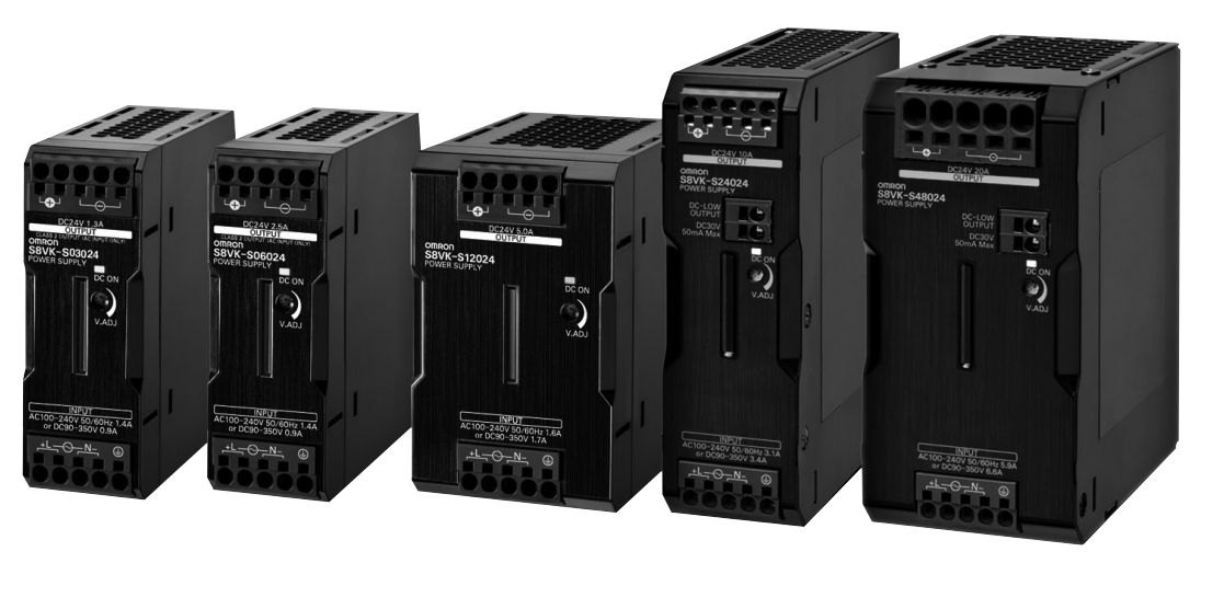
| 30 W | 100 to 240 VACallowable range:85 to 264 VAC or90 to 350 VDC) | 24 V | 1.3 A | 1.56 A | S8VK-S03024 |
| 60 W | 24 V | 2.5 A | 3 A | S8VK-S06024 | |
| 120 W | 24 V | 5 A | 6 A | S8VK-S12024 | |
| 240 W | 24 V | 10 A | 15 A | S8VK-S24024 | |
| 480 W | 24 V | 20 A | 30 A | S8VK-S48024 |
Mounting Brackets
| Name | Model |
|---|---|
| Front-mounting bracket (for 30 W and 60 W models) | S82Y-VS10F |
| Side-mounting bracket (for 30 W and 60 W models) | S82Y-VS10S |
| Front-mounting bracket (for 240 W and 480 W models) | S82Y-VK10F |

