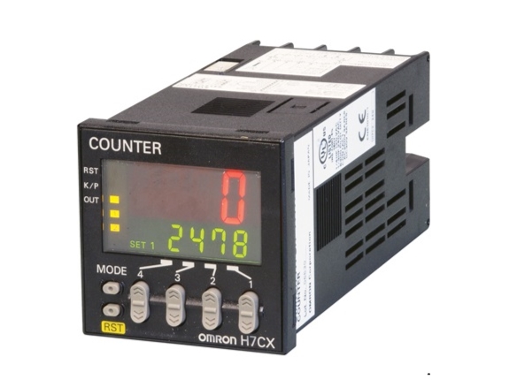
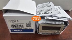
DIN 48 × 48 mm Multifunction Preset Counter with a Bright, Easy-to-view, Negative Transmissive LCD
Specification
| Models | H7CX-A114[]-N | H7CX-A11[]-N | H7CX-A4[]-N | |
|---|---|---|---|---|
| Classification | Preset counter | |||
| Configuration | 1-stage preset counter, 1-stage preset counter with total counter (selectable) *1 | |||
| Ratings | Power supply voltage*2 | • 100 to 240 VAC, 50/60 Hz • 24 VAC, 50/60 Hz or 12 to 24 VDC | • 100 to 240 VAC, 50/60 Hz • 12 to 24 VDC | |
| Operating voltage fluctuation range | 85% to 110% of rated supply voltage (12 to 24 VDC: 90% to 110%) | |||
| Power consumption | Approx. 9.4 VA at 100 to 240 VAC, Approx. 7.2 VA/4.7 W at 24 VAC/12 to 24 VDC, Approx. 3.7 W at 12 to 24 VDC | |||
| Mounting method | Flush mounting or surface mounting | Flush mounting | ||
| External connections | 11-pin socket | Screw terminals | ||
| Degree of protection | IEC IP66, UL508 Type 4X (indoors) for panel surface only and only when Y92S-29 Waterproof Packing is used. | |||
| Input signals | CP1, CP2, reset, and total reset | |||
| Counter | Maximum counting speed | 30 Hz (minimum pulse width: 16.7 ms) or 10 kHz (minimum pulse width: 0.05 ms) (selectable) (ON/OFF ratio 1:1) *Common setting for CP1 and CP2 | ||
| Input mode | Increment, decrement, increment/decrement (UP/DOWN A (command input), UP/DOWN B (individual inputs), or UP/DOWN C (quadrature inputs)) | |||
| Output mode | N, F, C, R, K-1, P, Q, A, K-2, D, and L. | |||
| One-shot output time | 0.01 to 99.99 s | |||
| Reset system | External (minimum reset signal width: 1 ms or 20 ms, selectable), manual, and automatic reset (internal according to C, R, P, and Q mode operation) | |||
| Tachometer | Refer to the separate table for tachometer function ratings. | |||
| Prescaling function | Yes (0.001 to 9.999) | Yes (0.001 to 99.999) | Yes (0.001 to 9.999) | |
| Decimal point adjustment | Yes (rightmost 3 digits) | |||
| Sensor waiting time | 290 ms max. (Control output is turned OFF and no input is accepted during sensor waiting time.) | |||
| Input method | No-voltage (NPN) input/voltage (PNP) input (switchable) No-voltage inputs: ON impedance: 1 kΩ max. (Leakage current: 12 mA at 0 Ω) ON residual voltage: 3 V max. OFF impedance: 100 kΩ min. Voltage input: High (logic) level: 4.5 to 30 VDC Low (logic) level: 0 to 2 VDC (Input resistance: approx. 4.7 kΩ) | |||
| External power supply | 12 VDC (±10%), 100 mA (except for H7CX-A[]D models) Refer to on page for details. | |||
| Control output | Contact output: 3 A at 250 VAC/30 VDC, resistive load (cosφ=1), Minimum applied load: 10 mA at 5 VDC (failure level: P, reference value) Transistor output: NPN open collector, 100 mA at 30 VDC, Residual voltage: 1.5 VDC max. (approx. 1 V), Leakage current: 0.1 mA max. | |||
| Display*3 | 7-segment, negative transmissive LCD Character height Count value: 12 mm (red) Set value: 6 mm (green) | 7-segment, negative transmissive LCD Character height Count value: 10 mm (red) Set value: 6 mm (green) | 7-segment, negative transmissive LCD Character height Count value: 12 mm (red, green, or orange selectable) Set value: 6 mm (green) | |
| Digits | 4 digits -999 to 9999 (-3 digits to +4 digits) | 6 digits -99999 to 999999 (-5 digits to +6 digits) | 4 digits -999 to 9999 (-3 digits to +4 digits) | |
| Memory backup | EEPROM (overwrites: 100,000 times min.) that can store data for 10 years min. | |||
| Operating temperature range | -10 to 55°C (-10 to 50°C if Counter/Tachometers are mounted side by side) (with no icing or condensation) | |||
| Storage temperature range | -25 to 70°C (with no icing or condensation) | |||
| Operating humidity range | 25% to 85% | |||
| Case color | Black (N1.5) (Optional Front Panels are available to change the Front Panel color to light gray or white.) | |||
| Attachments | --- | Flush mounting adapter, waterproof packing, terminal cover | ||
| Models | H7CX-A[]-N | H7CX-A4W[]-N | H7CX-AW[]-N/-AU[]-N | |
|---|---|---|---|---|
| Classification | Preset counter | Preset counter/tachometer | ||
| Configuration | 1-stage preset counter, 1-stage preset counter with total counter (selectable) *1 | 1-stage/2-stage preset counter, total and preset counter *1, batch counter, dual counter, and twin counter (selectable) | 1-stage/2-stage preset counter, total and preset counter *1, batch counter, dual counter, twin counter, and tachometer (selectable) | |
| Ratings | Power supply voltage*2 | • 100 to 240 VAC, 50/60 Hz • 12 to 24 VDC | • 100 to 240 VAC at 50/ 60 Hz • 24 VAC at 50/60 Hz or 12 to 24 VDC • 12 to 24 VDC | |
| Operating voltage fluctuation range | 85% to 110% of rated supply voltage (12 to 24 VDC: 90% to 110%) | |||
| Power consumption | Approx. 9.4 VA at 100 to 240 VAC, Approx. 7.2 VA/4.7 W at 24 VAC/12 to 24 VDC, Approx. 3.7 W at 12 to 24 VDC | |||
| Mounting method | Flush mounting | |||
| External connections | Screw terminals | |||
| Degree of protection | IEC IP66, UL508 Type 4X (indoors) for panel surface only and only when Y92S-29 Waterproof Packing is used. | |||
| Input signals | CP1, CP2, reset, and total reset | CP1, CP2, reset 1, and reset 2 | ||
| Counter | Maximum counting speed | 30 Hz (minimum pulse width: 16.7 ms) or 10 kHz (minimum pulse width: 0.05 ms) (selectable) (ON/OFF ratio 1:1) *Common setting for CP1 and CP2 | ||
| Input mode | Increment, decrement, increment/decrement (UP/DOWN A (command input), UP/DOWN B (individual inputs), or UP/DOWN C (quadrature inputs)) | |||
| Output mode | N, F, C, R, K-1, P, Q, A, K-2, D, and L. | N, F, C, R, K-1, P, Q, A, K-2, D, L, and H. | ||
| One-shot output time | 0.01 to 99.99 s | |||
| Reset system | External (minimum reset signal width: 1 ms or 20 ms, selectable), manual, and automatic reset (internal according to C, R, P, and Q mode operation) | |||
| Tachometer | Refer to the separate table for tachometer function ratings. | |||
| Prescaling function | Yes (0.001 to 99.999) | Yes (0.001 to 9.999) | Yes (0.001 to 99.999) | |
| Decimal point adjustment | Yes (rightmost 3 digits) | |||
| Sensor waiting time | 290 ms max. (Control output is turned OFF and no input is accepted during sensor waiting time.) | |||
| Input method | No-voltage (NPN) input/voltage (PNP) input (switchable) No-voltage inputs: ON impedance: 1 kΩ max. (Leakage current: 12 mA at 0 Ω) ON residual voltage: 3 V max. OFF impedance: 100 kΩ min. Voltage input: High (logic) level: 4.5 to 30 VDC Low (logic) level: 0 to 2 VDC (Input resistance: approx. 4.7 kΩ) | |||
| External power supply | 12 VDC (±10%), 100 mA (except for H7CX-A[]D models) Refer to on page for details. | |||
| Control output | Contact output: 3 A at 250 VAC/30 VDC, resistive load (cosφ=1), Minimum applied load: 10 mA at 5 VDC (failure level: P, reference value) Transistor output: NPN open collector, 100 mA at 30 VDC, Residual voltage: 1.5 VDC max. (approx. 1 V), Leakage current: 0.1 mA max. | |||
| Display*3 | 7-segment, negative transmissive LCD Character height Count value: 10 mm (red, green, or orange selectable) Set value: 6 mm (green) | 7-segment, negative transmissive LCD Character height Count value: 12 mm (red, green, or orange selectable) Set value: 6 mm (green) | 7-segment, negative transmissive LCD Character height Count value: 10 mm (red, green, or orange selectable) Set value: 6 mm (green) | |
| Digits | 6 digits -99999 to 999999 (-5 digits to +6 digits) | 4 digits -999 to 9999 (-3 digits to +4 digits) | 6 digits -99999 to 999999 (-5 digits to +6 digits), tachometer: 0 to 999999 | |
| Memory backup | EEPROM (overwrites: 100,000 times min.) that can store data for 10 years min. | |||
| Operating temperature range | -10 to 55°C (-10 to 50°C if Counter/Tachometers are mounted side by side) (with no icing or condensation) | |||
| Storage temperature range | -25 to 70°C (with no icing or condensation) | |||
| Operating humidity range | 25% to 85% | |||
| Case color | Black (N1.5) (Optional Front Panels are available to change the Front Panel color to light gray or white.) | |||
| Attachments | Flush mounting adapter, waterproof packing, terminal cover | Flush mounting adapter, waterproof packing, terminal cover, label for DIP switch settings | ||
*1. 1-stage preset counter and total counter functionality.
*2. Do not use the output from an inverter as the power supply.The ripple must be 20% maximum for DC power.
*3. The display is lit only when the power is ON. Nothing is displayed when power is OFF.
Tachometer Function Ratings
| Model | H7CX-A114[]-N H7CX-A11[]-N H7CX-A4[]-N H7CX-A[]-N H7CX-A4W[]-N | H7CX-AW[]-N/-AU[]-N | |||
|---|---|---|---|---|---|
| Input mode | No tachometer functionality | Selectable from independent measurements for 1 or 2 inputs, differential input for 2 inputs, absolute ratio for 2 inputs, and error ratio for 2 inputs. | |||
| Pulse measurement method | Periodic measurement | Pulse width measurement | |||
| Maximum counting speed | 30 Hz (minimum pulse width: 16.7 ms) | 1-input mode: 10 kHz (minimum pulse width: 0.05 ms) Other modes: 5 kHz (minimum pulse width: 0.1 ms) | 30 Hz (minimum pulse width: 16.7 ms) | 1-input mode: 10 kHz (minimum pulse width: 0.05 ms) Other modes: 5 kHz (minimum pulse width: 0.1 ms) | |
| Minimum input signal width | --- | --- | 30 ms *1 | 1-input mode: 0.2 ms Other modes: 0.4 ms * | |
| Measuring ranges | 0.001 to 30.00 Hz | 1-input mode: 0.001 to 10 kHz, Other modes: 0.01 to 5 kHz | 0.030 to 999999 s | 1-input mode: 0.0002 to 99999 s Other modes: 0.0004 to 99999 s | |
| Sampling period | 200 ms min. | 200 ms min. or continuous selectable (minimum interval of 10 ms) | Continuous (minimum interval of 10 ms) | ||
| Measuring accuracy | ±0.1% FS ±1 digit max. (at 23 ±5°C) | ||||
| Output mode | Input mode: Not 2-input independent measurement: HI-LO, AREA, HI-HI, LO-LO 2-input independent measurement: HI-HI, LO-LO | ||||
| Auto-zero time | 0.1 to 999.9s | ||||
| Startup time | 0.0 to 99.9s | ||||
| Averaging | Simple averaging/moving averaging selectable, Processing: OFF, 2, 4, 8, or 16 times | ||||
| Hold input | Minimum input signal width: 20 ms | ||||
Characteristics
| Insulation resistance | 100 MΩ min. (at 500 VDC) between current-carrying terminals and exposed non-current- carrying metal parts, and between non-continuous contacts | |
|---|---|---|
| Dielectric strength | 2,000 VAC, 50/60 Hz for 1 min between current-carrying metal parts and non-current- carrying metal parts 2,000 VAC, 50/60 Hz for 1 min between power supply and input circuit for all models except H7CX-[]D[] (1,000 VAC for 24 VAC/12 to 24 VDC) 1,000 VAC (for H7CX-[]SD[]), 50/60 Hz for 1 min between control output, power supply, and input circuit (2,000 VAC for models other than H7CX-[]SD[]) 1,000 VAC, 50/60 Hz for 1 min between non-continuous contacts | |
| Impulse withstand voltage | 3.0 kV between power terminals (1.0 kV for models with 24 VAC/12 to 24 VDC or 12 to 24 VDC) 4.5 kV between current-carrying terminals and exposed non-current-carrying metal parts (1.5 kV for models with 24 VAC/12 to 24 VDC or 12 to 24 VDC) | |
| Noise immunity | ±1.5 kV between power terminals (±480 V for models with 12 to 24 VDC) ±600 V between input terminals Square-wave noise by noise simulator (pulse width: 100 ns/1 μs, 1-ns rise) | |
| Static immunity | Malfunction: 8 kV Destruction: 15 kV | |
| Vibration resistance | Destruction | 10 to 55 Hz with 0.75-mm single amplitude each in three directions for 2 h each |
| Malfunction | 10 to 55 Hz with 0.35-mm single amplitude each in three directions for 10 min each | |
| Shock re-sistance | Destruction | 300 m/s2 each in three directions |
| Malfunction | 100 m/s2 each in three directions | |
| Life expectancy | Mechanical: 10,000,000 operations min. Electrical: 100,000 operations min. (3 A at 250 VAC, resistive load, ambient temperature condition: 23°C) * | |
| Weight | Approx. 130 g (Counter only) | |

