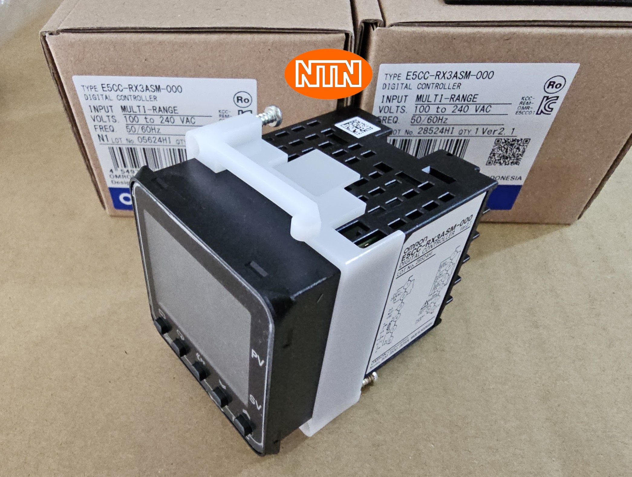
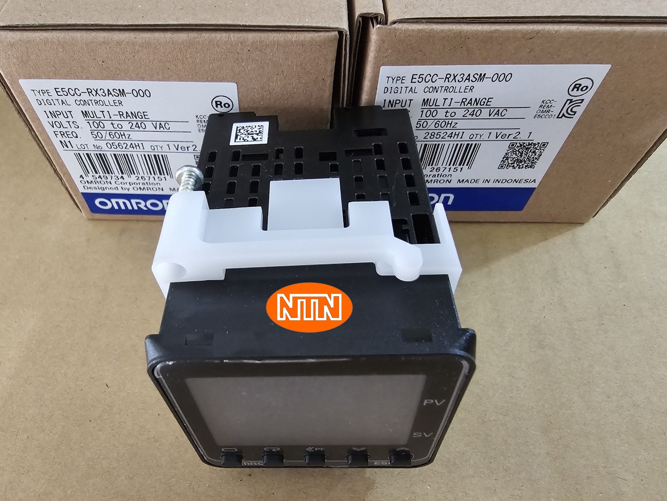
Bộ điều khiển nhiệt độ Omron E5CC-RX3ASM-000: Giới thiệu chi tiết
Tổng quan
Omron E5CC-RX3ASM-000 là một bộ điều khiển nhiệt độ kỹ thuật số nhỏ gọn, được thiết kế để điều khiển nhiệt độ trong các ứng dụng công nghiệp và dân dụng. Sản phẩm này nổi bật với độ tin cậy cao, dễ sử dụng và khả năng tương thích với nhiều loại cảm biến nhiệt độ khác nhau.
Đặc điểm nổi bật
- Thiết kế nhỏ gọn: Dễ dàng lắp đặt trong không gian hạn chế.
- Màn hình LCD: Hiển thị rõ ràng các thông số như nhiệt độ cài đặt, nhiệt độ thực tế.
- Nhiều loại đầu vào: Tương thích với nhiều loại cảm biến nhiệt độ như cặp nhiệt điện, nhiệt kế điện trở, cảm biến nhiệt hồng ngoại.
- Ngõ ra Relay: Điều khiển trực tiếp các thiết bị như rơ-le, contactor.
- Chức năng PID: Điều khiển nhiệt độ chính xác, ổn định.
- Dễ dàng cài đặt: Giao diện người dùng thân thiện, dễ sử dụng.
Ứng dụng
Bộ điều khiển nhiệt độ Omron E5CC-RX3ASM-000 được ứng dụng rộng rãi trong các lĩnh vực sau:
- Công nghiệp: Điều khiển nhiệt độ trong các quá trình sản xuất, máy móc thiết bị.
- Hệ thống sưởi và làm mát: Điều khiển nhiệt độ trong các tòa nhà, phòng sạch.
- Thiết bị gia dụng: Điều khiển nhiệt độ trong tủ lạnh, lò nướng, máy giặt.
- Các ứng dụng khác: Điều khiển nhiệt độ trong các phòng thí nghiệm, nhà kính
Specification
| Shape | DIN48 x 48 | |
|---|---|---|
| Fixed/Programmable | Fixed | |
| Power supply voltage | 100 to 240 VAC (50/60 Hz) | |
| Allowable voltage variable range | 85 to 110% of the power supply voltage | |
| Power consumption | 5.2 VA max. (at 100 to 240 VAC) | |
| Input | Number of input points | 1 point |
| Temperature input | Thermocouple: K, J, T, E, L, U, N, R, S, B, C/W, PLII Platinum resistance thermometer: Pt100, JPt100 Infrared Thermosensor: 10 to 70 ℃, 60 to 120 ℃, 115 to 165 ℃, 140 to 260 ℃ | |
| Analog input | 4 to 20 mA, 0 to 20 mA, 1 to 5 V, 0 to 5 V, 0 to 10 V | |
| Input impedance | Current input: 150 Ω max., voltage input: 1 MΩ min. (Applicable when connecting 1:1 to ES2-HB-N/THB-N.) | |
| Control method | ON/OFF or 2-PID control with auto-tuning | |
| Control output | Number of total control output | 1 point |
| Control output 1 | Relay output | |
| Control output 2 | None | |
| Relay output | 1 point SPST-NO, 250 VAC, 3 A (resistive load) Minimum applicable load: 10 mA at 5 V | |
| Auxiliary output | Number of total auxiliary output | 3 point |
| Relay output | SPST-NO, 250 VAC, 2 A (resistive load), electrical life: 100,000 operations (minimum applicable load: 5 V, 10 mA) | |
| Setting method | Digital setting using front panel keys | |
| Indication method | 11-segment digital display and individual indicators | |
| Multi SP functions | Up to eight set points (SP0 to SP7) can be saved and selected using key operations. | |
| Sampling period | 50 ms | |
| Hysteresis | Temperature input: 0.1 to 999.9 ℃ or °F (in units of 0.1 ℃ or °F) Analog input: 0.01 to 99.99% FS (in units of 0.01% FS) | |
| Proportional band | Temperature input: 0.1 to 999.9 ℃ or °F (in units of 0.1 ℃ or °F) Analog input: 0.1% to 999.9% FS (in units of 0.1% FS) | |
| Integral time | 0 to 9999 s (in units of 1 s), 0.0 to 999.9 s (in units of 0.1 s) | |
| Derivative time | 0 to 9999 s (in units of 1 s), 0.0 to 999.9 s (in units of 0.1 s) | |
| for cooling | Proportional band (P) | Temperature input: 0.1 to 999.9 ℃ or °F (in units of 0.1 ℃ or °F) Analog input: 0.1% to 999.9% FS (in units of 0.1% FS) |
| Integral time (I) | 0 to 9999 s (in units of 1 s), 0.0 to 999.9 s (in units of 0.1 s) | |
| Derivative time (D) | 0 to 9999 s (in units of 1 s), 0.0 to 999.9 s (in units of 0.1 s) | |
| Control period | 0.1 s, 0.2 s, 0.5 s, 1 to 99 s (in units of 1 s) | |
| Manual reset value | 0.0 to 100.0% (in units of 0.1%) | |
| Insulation resistance | 20 MΩ min. (at 500 VDC) | |
| Dielectric strength | 3,000 VAC 50/60 Hz 1 min (Between current-carrying terminals of different polarity) | |
| Vibration resistance | Destruction: 10 to 55 Hz, 20 m/s2 for 2 h each in X, Y, and Z directions Malfunction: 10 to 55 Hz, 20 m/s2 for 10 min each in X, Y, and Z directions | |
| Shock resistance | Destruction: 300 m/s2, 3 times each in X, Y, and Z directions Malfunction: 100 m/s2, 3 times each in X, Y, and Z directions | |
| Ambient temperature (Operating) | -10 to 55 ℃ (with no freezing or condensation) For 3-year warranty with standard mounting: -10 to 50 ℃ (with no freezing or condensation) | |
| Ambient temperature (Storage) | -25 to 65 ℃ (with no freezing or condensation) | |
| Ambient humidity (Operating) | 25 to 85 % | |
| Altitude | 2000 m max. | |
| Degree of protection | Front panel: IP66, Rear case: IP20, Terminal section: IP00 | |
| Memory protection | Non-volatile memory (number of writes: 1,000,000) | |
| Case color | Black | |
| Terminal type | Screw terminal block | |
| Accessories | Mounting adapter, Waterproof packing | |
| Weight | Main Unit: Approx. 120 g Adapter: Approx. 10 g | |
| Sold separately | USB Serial Conversion Cable: E58-CIFQ2 Terminal Cover: E53-COV17/E53-COV23 Waterproof packing: Y92S-P8 Adapter: Y92F-45/Y92F-49 Waterproof Cover: Y92A-48N DIN track mounting adapter: Y92F-52 Hard Front Cover: Y92A-48H Soft Front Cover: Y92A-48D CX-Thermo Support Software: EST2-2C-MV4 | |
| Indication accuracy | Thermocouple: (±0.3% of indicated value or ±1 ℃, whichever is greater) ±1 digit max. Platinum resistance thermometer: (±0.2% of indicated value or ±0.8 ℃, whichever is greater) ±1 digit max. Analog input: ±0.2% FS ±1 digit max. (The indication accuracy of K thermocouples in the -200 to 1300 ℃ range, T and N thermocouples at a temperature of -100 ℃ max., and U and L thermocouples at any temperatures is ±2 ℃ ±1 digit max. B thermocouple at a temperature of 400 ℃ max. is not specified. B thermocouples in the 400 to 800 ℃ range is ±3 ℃ max. R and S thermocouples at a temperature of 200 ℃ max. is ±3 ℃ ±1 digit max. C/W thermocouples is (±0.3% PV or ±3 ℃, whichever is greater) ±1 digit max. PL II thermocouples is (±0.3% PV or ±2 ℃, whichever is greater) ±1 digit max.) |
|---|---|
| Influence of temperature/voltage | Thermocouple: R, S, B, C/W, and PLII: (±1% of indicated value or ±10 ℃, whichever is greater) ±1 digit max. Others: (±1% of indicated value or ±4 ℃, whichever is greater) ±1 digit max.. However K thermocouple at -100 ℃ max.: ±10 ℃ max. Platinum resistance thermometer: (±1% of indication value or ±2 ℃, whichever is greater) ±1 digit max. Analog input: ±1% FS ±1 digit max. Ambient temperature: -10 to 23 to 55 ℃, Voltage range: -15 to 10% of rated voltage |
| Influence of EMS. | Thermocouple: R, S, B, C/W, and PLII: (±1% of indicated value or ±10 ℃, whichever is greater) ±1 digit max. Others: (±1% of indicated value or ±4 ℃, whichever is greater) ±1 digit max.. However K thermocouple at -100 ℃ max.: ±10 ℃ max. Platinum resistance thermometer: (±1% of indication value or ±2 ℃, whichever is greater) ±1 digit max. Analog input: ±1% FS ±1 digit max. |
| Influence of signal source resistance | Thermocouple: 0.1℃/Ω max. (100 Ω max.) Platinum resistance thermometer: 0.1℃/Ω max. (10 Ω max.) |
